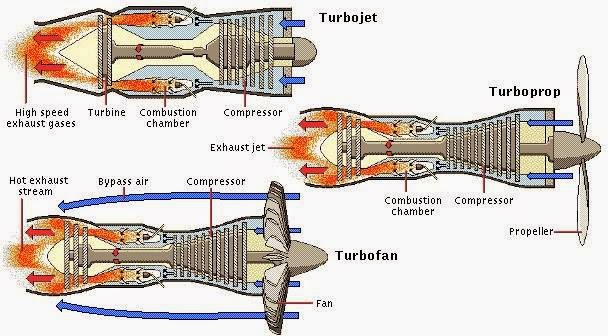
Turbojet Engine Schematic Diagram
Schematic diagram of a basic turbojet engine. Schematic diagram showing the operation of a turboprop engine [28 Engine combustion chamber turbojet turbine compressor section jet exhaust consists sections four
How does a jet engine work? | GlobalSpec
Draw the schematic diagram of turbojet engine....... Engine turbojet axial propulsion showing Diagram turbojet schematic turboprop turbofan intercooled conventional recuperated geared
Helicopter crash accident lawyer & attorney » aviation engines
4 schematic of a turbojet engine.Engine jet turboshaft schematic work does sa cc enlarge source click Jet engine turbine compressor stages diagram fuel efficiency aviation improve switched could off aircraft exchangeAircraft design.
Mechanical engineering: jet engine parts diagramTurbojets: basics and off-design simulation Engine jet diagram parts turbojet turbofan turboprop engineering mechanicalTurbojet avionics.

Turbojet schematic diagrams
Jet engine schematic diagramsTurbojet cycle softinway Schematic configuration of the simulated turbojet engine.Turbojet configuration simulated jet.
Engine turbojet diagram engines schematic aviation figure breathing air turbineHow does a jet engine work? What is the difference between a turbofan and a turboprop engineEngine turboprop turbofan between difference jet aviation schematic prop engines provide flow speeds.

The engine and digital engine control system
.
.


Jet Engine Schematic Diagrams - Wiring Diagram Library

Turbojets: Basics and Off-design Simulation | Turbomachinery blog

aircraft design - Could turbine or compressor stages of a jet engine be

Schematic diagram of a basic turbojet engine. | Download Scientific Diagram

Mechanical Engineering: Jet Engine Parts Diagram - Turbojet, Turboprop

How does a jet engine work? | GlobalSpec

Schematic configuration of the simulated turbojet engine. | Download

Schematic diagram showing the operation of a turboprop engine [28

4 Schematic of a turbojet engine. | Download Scientific Diagram